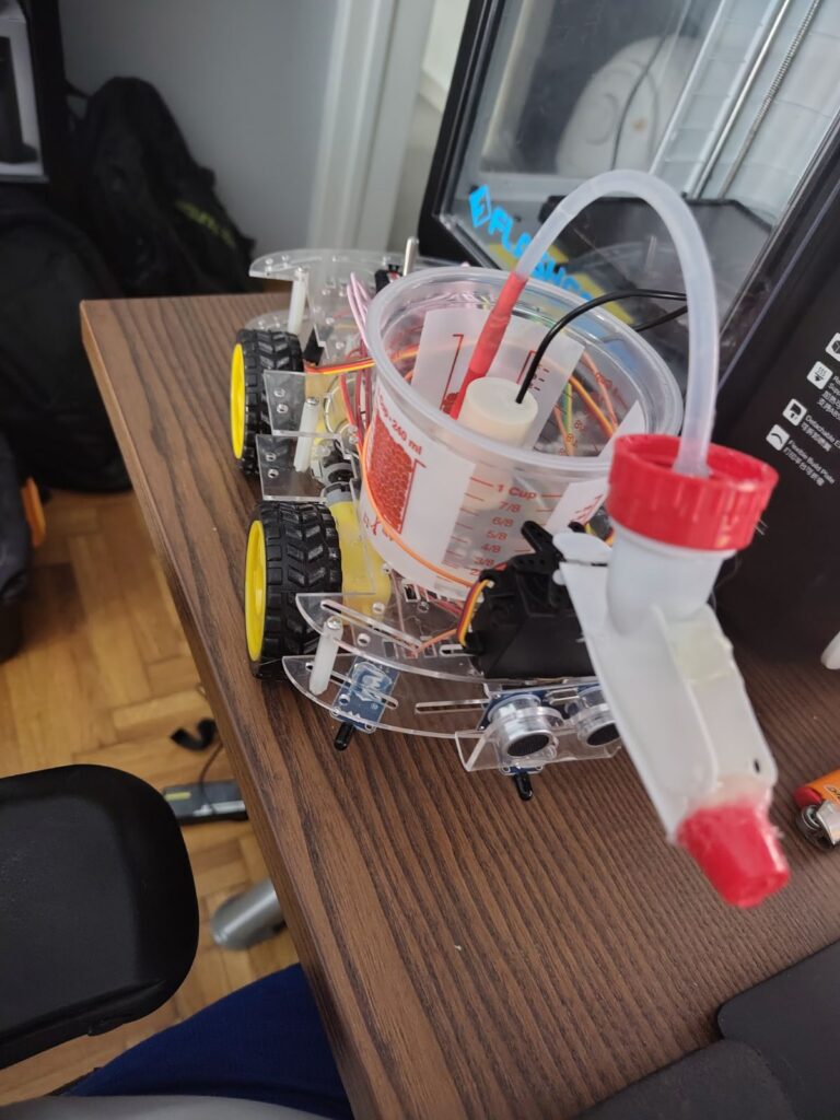
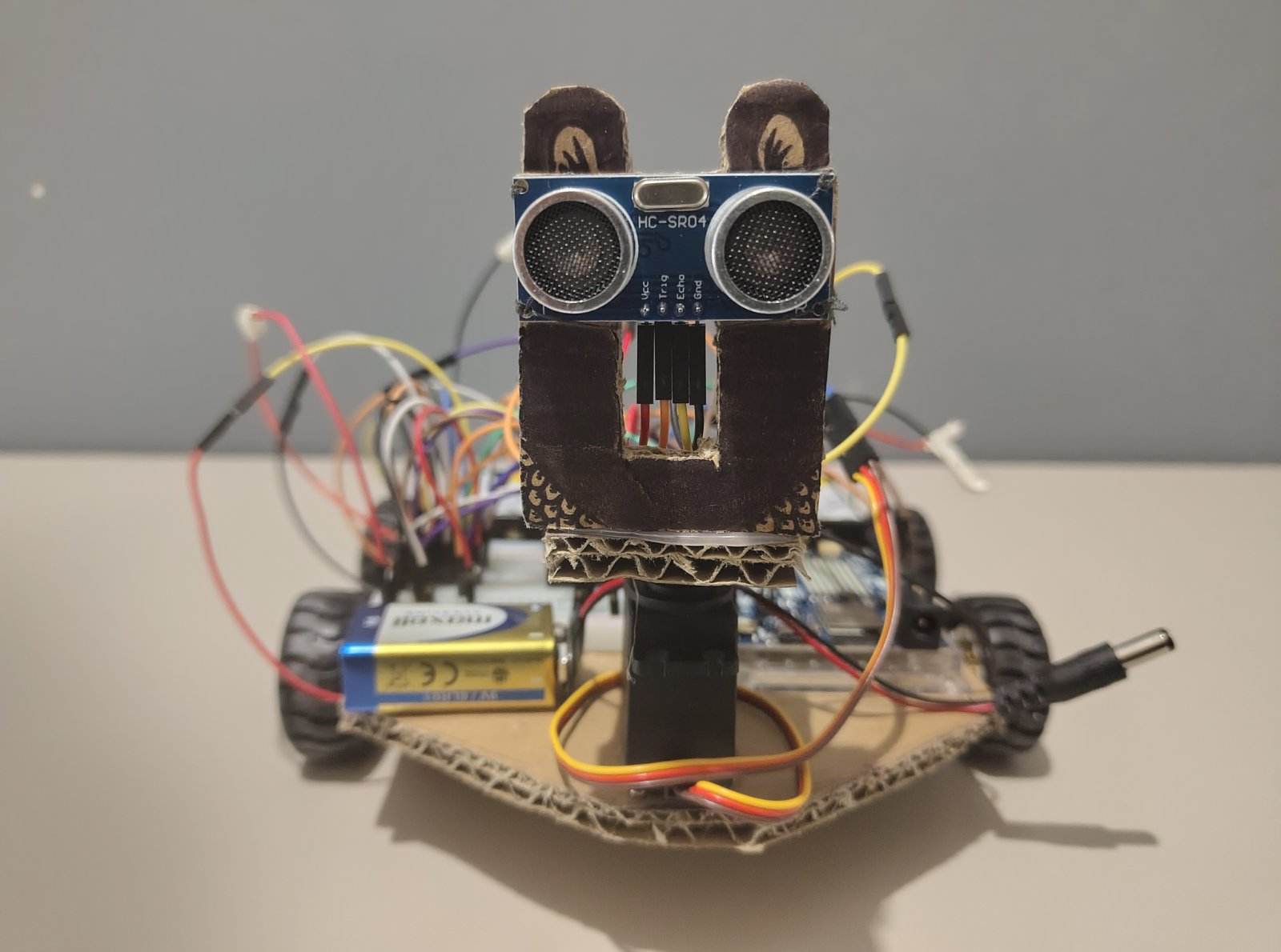
This project was developed as part of a Master’s degree at the University of West Attica (UniWA). The goal was to design and build a small autonomous UGV (Unmanned Ground Vehicle) from scratch using an Arduino microcontroller, DC motors and an ultrasonic sensor, a robot that can move through an environment and avoid obstacles entirely on its own.
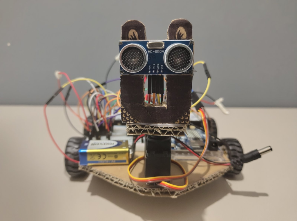
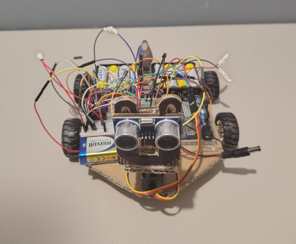
We named it Frankenbot, partly because it was assembled from a collection of different parts and partly because it takes on a life of its own once you power it up.
The full source code is available on GitHub.
1. What Are We Building?
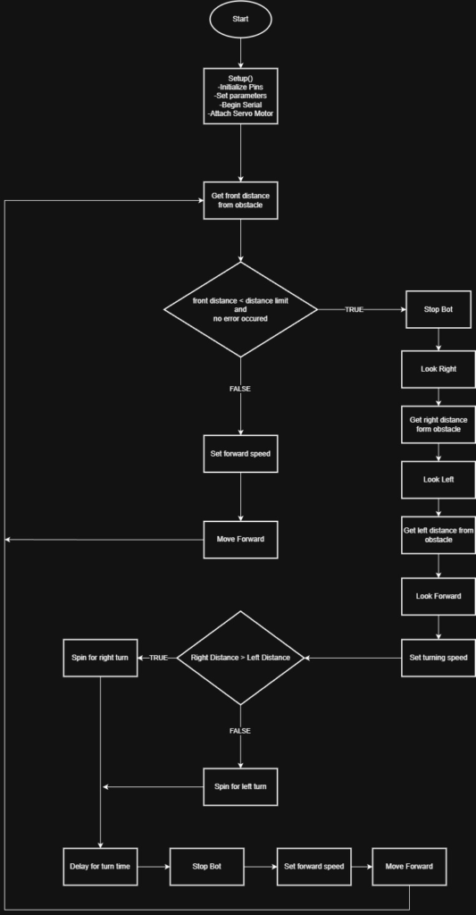
Frankenbot is a four-wheeled ground robot that drives forward autonomously. When it detects an obstacle closer than 30 cm ahead, it stops, rotates its ultrasonic sensor left and right to scan for the clearest path and then turns in that direction before resuming its forward motion.
The key components are:
- An Arduino Uno R4 WiFi as the brain.
- An HC-SR04 ultrasonic sensor mounted on a servo for distance scanning.
- A MG996R servo motor to rotate the sensor left and right.
- Four N20 Micro Metal Gear DC motors for movement.
- Two L293D motor driver ICs to control the motors.
2. The Hardware
Arduino Uno R4 WiFi
The Arduino Uno R4 WiFi is the controller at the heart of Frankenbot. It features an ARM Cortex-M4 microprocessor and provides the digital I/O pins needed to interface with sensors, motor drivers and the servo. It is powered by a 9V battery through the barrel jack, which it regulates internally down to 5V for its logic and peripherals.
Ultrasonic Sensor: HC-SR04
The HC-SR04 works like sonar. It emits a short ultrasonic pulse via its TRIG pin, which then bounces off any surface in front of it and returns to the ECHO pin. By measuring how long the echo takes to return and knowing the speed of sound (~343 m/s), we can calculate the distance to the obstacle. It operates at 5V and is well suited for short-to-medium range detection (2 cm – 400 cm).
Servo Motor: MG996R
The MG996R servo is a high-torque servo used to pan the ultrasonic sensor horizontally. When an obstacle is detected ahead, the servo sweeps the sensor to 0° (right) and 180° (left) so FrankenBot can measure the available space in each direction and choose where to turn.
Motor Drivers: L293D
The Arduino’s GPIO pins cannot supply the current required to drive DC motors directly. The L293D is an H-bridge motor driver IC that solves this: it takes a low-current control signal from the Arduino and switches a higher-current motor supply accordingly. Each L293D can independently control two DC motors, so we use two chips for our four motors.
Drive Motors: N20 Micro Metal Gear Motors
Frankenbot uses four 6V N20 DC motors with internal metal gearboxes. The gearboxes reduce the output speed (down to ~300 RPM) while multiplying the torque, giving the robot the grip and pulling power it needs. The motors are powered by a separate external battery pack, not the Arduino’s regulator, to avoid voltage drops affecting the logic.
3. The Circuit
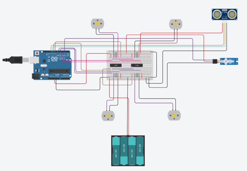
The wiring connects all of these components to the Arduino according to the following pin assignments:
| Component | Arduino Pin |
| Servo signal | D3 |
| Ultrasonic TRIG | D12 |
| Ultrasonic ECHO | D11 |
| Left motor ENABLE (PWM) | D10 |
| Right motor ENABLE (PWM) | D9 |
| Left motor IN1 | D7 |
| Left motor IN2 | D6 |
| Right motor IN1 | D5 |
| Right motor IN2 | D4 |
A few important notes about the circuit:
- The ENABLE pins (D9 and D10) are PWM-capable pins. By writing an analog value (0–255) to them, we control the motor speed.
- The IN1/IN2 pairs for each motor control direction. Setting IN1 HIGH and IN2 LOW drives the motor forward; flipping them reverses it. Setting both LOW stops the motor.
- The motor power is supplied from an external battery directly to the L293D’s motor supply pins, not from the Arduino’s 5V output. This is critical to avoid brownouts in the Arduino logic.
4. The logic flow
Here is a summary of the decision loop:
5. The Code
#include <Servo.h>

// ---------------- PIN DEFINITIONS ----------------
const uint8_t SERVO_PIN   = 3;
const uint8_t TRIGGER_PIN = 12;
const uint8_t ECHO_PIN    = 11;

const uint8_t LEFT_ENABLE  = 10;   // PWM
const uint8_t RIGHT_ENABLE = 9;    // PWM

const uint8_t LEFT_MOTOR_PIN1  = 7;
const uint8_t LEFT_MOTOR_PIN2  = 6;
const uint8_t RIGHT_MOTOR_PIN1 = 5;
const uint8_t RIGHT_MOTOR_PIN2 = 4;

// ---------------- TUNING ----------------
const uint16_t DISTANCE_LIMIT_CM = 30;
const uint16_t TURN_TIME_MS      = 700;
const uint16_t NO_ECHO_CM        = 999;

const uint16_t PING_TIMEOUT_US   = 30000; // Timeout for pulseIn
const uint8_t  PING_SAMPLES      = 5;     // Median of 5
const uint16_t PING_GAP_MS       = 40;    // Gap between pings

const uint16_t SERVO_SETTLE_MS   = 500;   // Time for servo to settle

// Speeds (0..255). Tune these to reduce overshoot / slipping.
const uint8_t SPEED_FWD  = 210;
const uint8_t SPEED_TURN = 180;

// ---------------- GLOBALS ----------------
Servo servo_motor;

// ---------------- MOTOR CONTROL ----------------
void setSpeed(uint8_t left, uint8_t right)
{
  analogWrite(LEFT_ENABLE, left);
  analogWrite(RIGHT_ENABLE, right);
}

void driveLeft(int8_t dir)
{
  // Direction: +1 forward, -1 backward, 0 stop
  if (dir > 0)
  {
    digitalWrite(LEFT_MOTOR_PIN1, HIGH);
    digitalWrite(LEFT_MOTOR_PIN2, LOW);
  }
  else if (dir < 0)
  {
    digitalWrite(LEFT_MOTOR_PIN1, LOW);
    digitalWrite(LEFT_MOTOR_PIN2, HIGH);
  }
  else
  {
    digitalWrite(LEFT_MOTOR_PIN1, LOW);
    digitalWrite(LEFT_MOTOR_PIN2, LOW);
  }
}

void driveRight(int8_t dir)
{
  if (dir > 0)
  {
    digitalWrite(RIGHT_MOTOR_PIN1, LOW);
    digitalWrite(RIGHT_MOTOR_PIN2, HIGH);
  }
  else if (dir < 0)
  {
    digitalWrite(RIGHT_MOTOR_PIN1, HIGH);
    digitalWrite(RIGHT_MOTOR_PIN2, LOW);
  }
  else
  {
    digitalWrite(RIGHT_MOTOR_PIN1, LOW);
    digitalWrite(RIGHT_MOTOR_PIN2, LOW);
  }
}

void moveForward()
{
  driveLeft(+1);
  driveRight(+1);
}

void stopCar()
{
  driveLeft(0);
  driveRight(0);
}

void turnLeftSpin()
{
  // Spin-in-place left: left backward, right forward
  driveLeft(-1);
  driveRight(+1);
}

void turnRightSpin()
{
  // Spin-in-place right: left forward, right backward
  driveLeft(+1);
  driveRight(-1);
}

// ---------------- ULTRASONIC ----------------
uint16_t pingOnceCm()
{
  digitalWrite(TRIGGER_PIN, LOW);
  delayMicroseconds(2);
  digitalWrite(TRIGGER_PIN, HIGH);
  delayMicroseconds(10);
  digitalWrite(TRIGGER_PIN, LOW);

  unsigned long duration = pulseIn(ECHO_PIN, HIGH, PING_TIMEOUT_US);
  if (duration == 0)
  {
    return NO_ECHO_CM;
  }

  return (uint16_t)((duration * 343UL) / 20000UL);
}

uint16_t getDistanceCm()
{
  uint16_t v[PING_SAMPLES];

  // Take PING_SAMPLES times ping values
  for (uint8_t i = 0; i < PING_SAMPLES; i++)
  {
    v[i] = pingOnceCm();
    delay(PING_GAP_MS);
  }

  // Sort the array with ping values
  for (uint8_t i = 0; i < PING_SAMPLES - 1; i++)
  {
    for (uint8_t j = i + 1; j < PING_SAMPLES; j++)
    {
      if (v[j] < v[i])
      {
        uint16_t t = v[i];
        v[i] = v[j];
        v[j] = t;
      }
    }
  }

  // Return the median value in the center of the array
  return v[PING_SAMPLES / 2];
}

// ---------------- SERVO LOOK ----------------
void lookTo(uint8_t angle)
{
  // Do not let angles over 180 degrees
  if (angle > 180)
  {
    angle = 180;
  }

  servo_motor.write(angle);
  delay(SERVO_SETTLE_MS);
}

// ---------------- SETUP / LOOP ----------------
void setup()
{
  // Start serial monitor for debugging purposes
  Serial.begin(9600);

  // Set the enables for the L293D ICs
  pinMode(LEFT_ENABLE, OUTPUT);
  pinMode(RIGHT_ENABLE, OUTPUT);

  // Set the motor pins
  pinMode(LEFT_MOTOR_PIN1, OUTPUT);
  pinMode(LEFT_MOTOR_PIN2, OUTPUT);
  pinMode(RIGHT_MOTOR_PIN1, OUTPUT);
  pinMode(RIGHT_MOTOR_PIN2, OUTPUT);

  // Set the ultrasonic
  pinMode(TRIGGER_PIN, OUTPUT);
  pinMode(ECHO_PIN, INPUT);

  // Set the servo motor
  servo_motor.attach(SERVO_PIN);
  lookTo(90);

  // Start with controlled speed
  setSpeed(SPEED_FWD, SPEED_FWD);

  delay(300);
}

void loop()
{
  uint16_t front = getDistanceCm();

  Serial.print("Front cm: ");
  Serial.println(front);

  // Check distance to the front if smaller than the limit
  if (front != NO_ECHO_CM && front < DISTANCE_LIMIT_CM)
  {
    // Stop the car
    stopCar();
    delay(200);

    // Start looking right
    Serial.println("Looking RIGHT...");
    lookTo(0);

    // Measure the distance on the right in cm
    uint16_t rightDist = getDistanceCm();

    Serial.print("Right cm: ");
    Serial.println(rightDist);

    // Start looking left
    Serial.println("Looking LEFT...");
    lookTo(180);

    // Measure the distance on the left in cm
    uint16_t leftDist = getDistanceCm();

    Serial.print("Left cm: ");
    Serial.println(leftDist);

    // Look forward
    Serial.println("Center...");
    lookTo(90);

    // Set the turn speed. It is set lower to be more precise
    setSpeed(SPEED_TURN, SPEED_TURN);

    // Check where there is more space to travel
    if (rightDist > leftDist)
    {
      Serial.println("Turning RIGHT (spin)...");
      turnRightSpin();
    }
    else
    {
      Serial.println("Turning LEFT (spin)...");
      turnLeftSpin();
    }

    delay(TURN_TIME_MS);

    // Stop the car
    stopCar();
    delay(100);

    // Set the speed to moving
    setSpeed(SPEED_FWD, SPEED_FWD);

    // Move forward to the new direction
    moveForward();
  }
  else
  {
    // Set the speed to moving
    setSpeed(SPEED_FWD, SPEED_FWD);

    // Move forward to the same direction
    moveForward();
  }

  // A small delay before every loop to finish everything
  delay(50);
}
6. It’s Alive!
7. What We Learned
Building Frankenbot from scratch taught us several practical lessons that go beyond Arduino basics:
Noise in sensor data is real. A single ultrasonic reading is often unreliable. The median filter over 5 samples made the robot’s behaviour noticeably more stable and less twitchy.
Motor speed asymmetry matters. If both sides are given identical PWM values, the robot rarely drives in a perfectly straight line, small differences in motor characteristics or wheel grip cause it to drift. Fine-tuning the speed constants can compensate for this.
Servo settle time is not optional. Early versions of the code didn’t wait long enough for the servo to reach its target position, leading to the robot turning in the wrong direction because it measured distance at the wrong angle.
Power isolation is critical. Running the DC motors from the Arduino’s 5V rail caused voltage drops that reset the board. Separating the motor power supply immediately fixed the instability.